Minecraft version
Back to mods 
CurseForge · Minecraft mod
ElectroFlow(Voltaria)
ElectroFlow brings electricity closer to reality—generate, manage, and transform energy! Build incredible automated systems, use aesthetically pleasing cables, create your own city, and construct your very own power plant.
Choose a version Pick your version below, then grab the matching file.
Quick answer
Which ElectroFlow(Voltaria) release should I use?
Latest stable file electroflowvoltaria-1.0.0-beta-mc1.21.1.jar
Game version 1.21.1
Loader NeoForge
ElectroFlow(Voltaria) electroflowvoltaria-1.0.0-beta-mc1.21.1.jar targets 1.21.1 with NeoForge. The project page does not say whether this file belongs on the client, dedicated server, or both. No extra mods listed for this file.
Where it goes
Is ElectroFlow(Voltaria) required on the client, server, or both?
The project page does not say whether this file belongs on the client, dedicated server, or both.
Client Source doesn’t say
Dedicated server Source doesn’t say
Loader for this release NeoForge
Required install it here Optional supported, not mandatory Not supported do not install here Source doesn’t say do not assume
The source does not explicitly classify this release as client-only or server-only.
What else does ElectroFlow(Voltaria) electroflowvoltaria-1.0.0-beta-mc1.21.1.jar need?
electroflowvoltaria-1.0.0-beta-mc1.21.1.jar. Change the file and its required mods may change too.
This file does not list any required mods. Do not add a library just because a different file uses it.
This file does not list any required or optional mods.
Before you install it
Add ElectroFlow(Voltaria) without breaking your instance.
Built for ElectroFlow(Voltaria) electroflowvoltaria-1.0.0-beta-mc1.21.1.jar. Pick another file and the loader, install side or required mods may change.
- 01
Stick to this file
Use electroflowvoltaria-1.0.0-beta-mc1.21.1.jar. It targets 1.21.1 with NeoForge; another release may have different loader, side or dependency requirements.
- 02
Bring the mods it needs
This file does not list any required mods. Do not add a library just because a different file uses it.
- 03
Put it on the correct side
The project page does not say whether this file belongs on the client, dedicated server, or both.
- 04
Pick the file you checked
Use the “Get this file” button beside electroflowvoltaria-1.0.0-beta-mc1.21.1.jar. It opens that exact file at the source.
About this project
What does ElectroFlow(Voltaria) add?
 Welcome to the ElectroFlow mod! It might seem confusing at first, but you’ll quickly get the hang of it. Energy can travel even when a chunk isn’t loaded—which means you can set up solar or wind farms far away and still make use of the power. The mod is currently in beta! AI Alert: AI was used for translation into other languages and to assist with coding, but this mod was made with love <3 Compatibility:
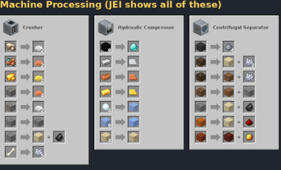
- JEI: categories for the crusher, compressor and centrifuge; the electric furnace and coal generator show up as catalysts.
- Other mods' storage and fluids: belts, tubes, funnels, arms, pipes, pumps and tanks all use NeoForge capabilities (chests, barrels, drawers, AE2, Refined Storage, tanks and pipes from other mods…).
- Languages: English, Brazilian Portuguese, Spanish (ES/MX/AR) and Simplified Chinese.
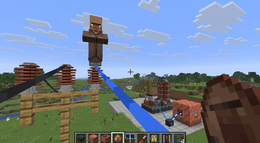
----- Electric shock that makes sense
- Body current = voltage ÷ (body + ground resistance). Standing in water is deadly; standing on wool or glass is not.
- A bird on a wire is safe — touching the ground is what kills you.
- High voltage (≥ 1 kV) arcs through the air and through insulation.
- Metal armor (iron, chainmail, copper, gold, netherite) makes shocks much worse.
 Power generation
- Solar panels (100 W and 400 W) with a real I-V curve that follows the sun.
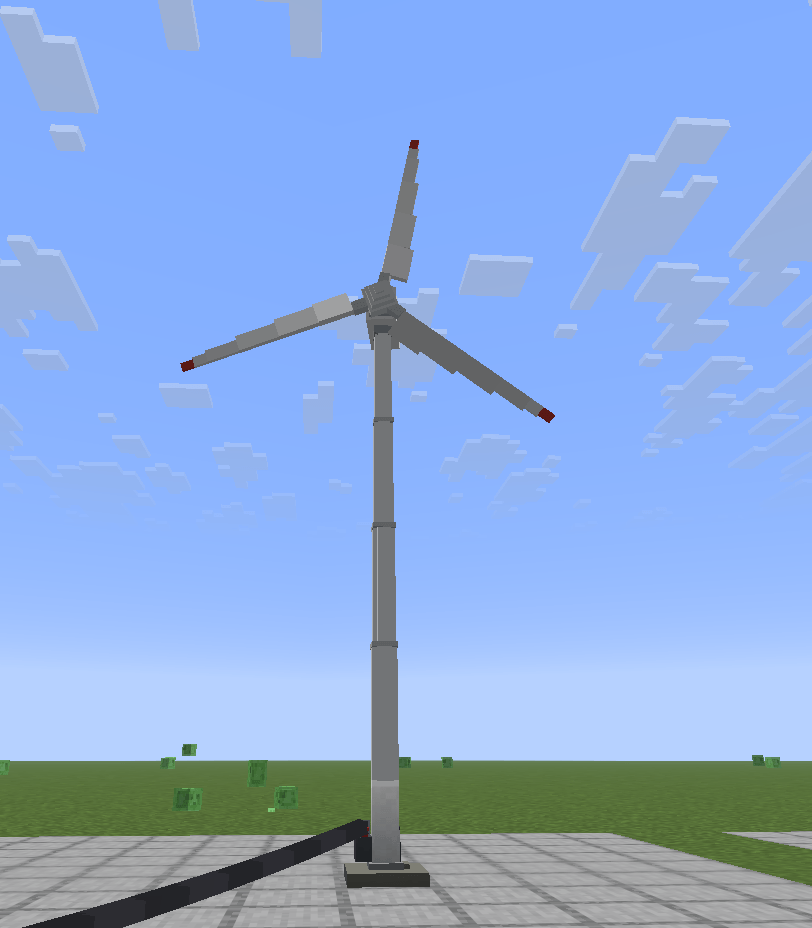
- Wind turbine (3 kW): a 7.5-block tower with a 6 m rotor that turns to face the wind. World wind changes direction and gusts; power follows P = ½·ρ·A·Cp·v³, grows with height, and is blocked by trees and buildings.
- Coal generator (5 kW, 220 V AC): burns any furnace fuel according to the load.
- Build-your-own battery (multiblock of cells) at 12, 24 or 48 V, with a monitor showing charge and power.
 Buildable Battery — step by step
What you need
| Block | Where it goes | What it does |
|---|---|---|
| Copper block (vanilla — any oxidation stage, waxed or not, plain or cut) | walls, floor, roof and corners | the casing |
| Glass / tinted glass (optional) | walls | a window to see the cells |
| Battery Cell | inside | stores 5 kWh each |
| Input Port | walls | where energy comes IN (panels, generators) |
| Output Port | walls | where energy goes OUT (inverter, 12 V lamp) |
| Battery Monitor (only 1) | walls | forms the battery and shows charge, kWh and watts |
Size: from 3×3×3 up to 9×9×9. A 3×3×3 holds 1 cell (5 kWh), a 5×5×5 holds 27 (135 kWh) and a 9×9×9 holds 343 (1,715 kWh).
- Step 1 — copper floor and walls
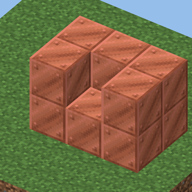
Step 2 — cells inside: 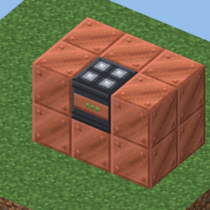 Fill the inside with Battery Cells. You can leave some air inside, but only the cells count. Each one adds 5 kWh and lowers the internal resistance, so a bigger battery can deliver more current without its voltage sagging. Step 3 — close it with the ports and the monitor
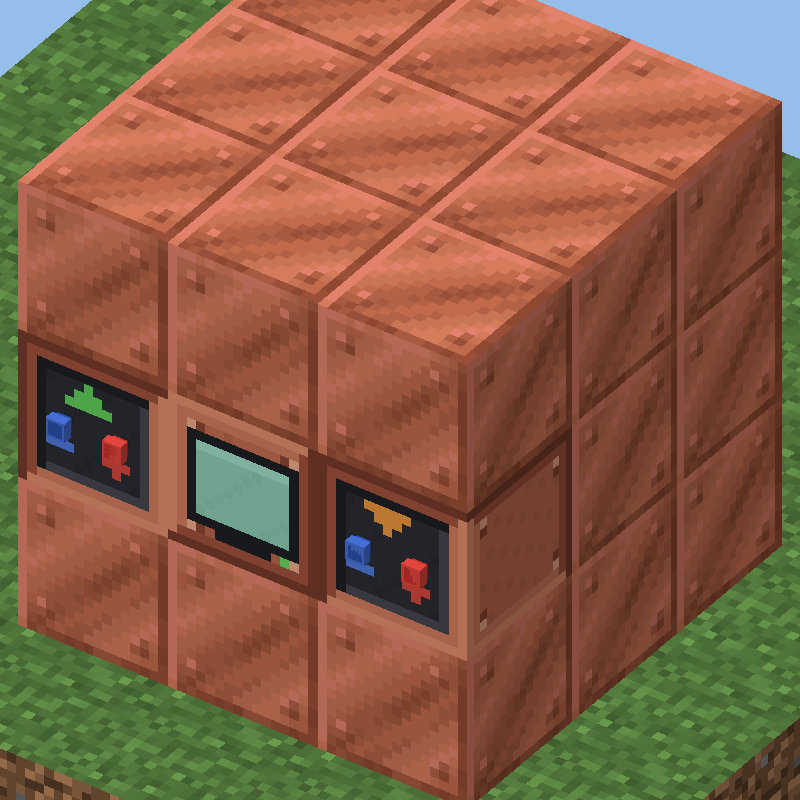
- Close the roof and the front. On the walls, place the Input Port, the Monitor and the Output Port in place of copper blocks.
- The ports can go on any wall: sides, front, back, roof or floor, and input and output can be on different faces. Their terminals (red + and blue −) always face out of the box. If they end up crooked when you place them, the monitor straightens them when the battery forms.
- The monitor re-checks the structure every 2 seconds. When its screen changes from "INCOMPLETE" to a percentage, the battery is formed.
- Right-click the monitor to see its size, number of cells, capacity, charge and voltage in chat — or why it didn't form, with the coordinates of the wrong block.
- Shift + right-click the monitor to change the bank voltage (12 → 24 → 48 V). Default: 12 V.
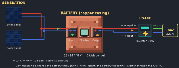
Bank voltage vs. panels (important)
The Input Port only charges when the outside voltage is HIGHER than the battery's, just like in real life. So:
| Bank | Real voltage (empty → full) | Panels that can charge it |
|---|---|---|
| 12 V | 10.5 → 12.8 V | small panels in parallel (18.6 V each) |
| 24 V | 21 → 25.6 V | 2 small panels in SERIES (37 V) or 1 large panel (41.5 V) |
| 48 V | 42 → 51.2 V | 2 large panels in series (83 V) or 4 small panels in series (74 V) |
A higher bank voltage means less current for the same power, so thinner cables can handle it. 3 kW at 12 V is 250 A, which melts thin cables; at 48 V it's only ~62 A.
How it works inside
- Input: built-in charge controller. It switches on when the outside voltage rises above the battery's and cuts off when the battery is full (100 %) or when current would flow back (at night the panels don't drain the battery).
- Output: direct connection. It cuts off by itself at 2 % charge to protect the cells.
- Voltage rises with charge (87.5 % → 106.7 % of nominal), just like the mod's 12 V battery.
- Monitor screen: charge % and bank voltage / stored kWh / power (+ charging, − discharging). Green = charging, orange = discharging.
- The energy is stored in the monitor. Breaking the monitor loses the stored energy.
---------- Buildable Transformer — step by step A single-phase transformer that you build block by block. It steps voltage up so you can send power far away through thin cables, or steps it down so you can use it again. 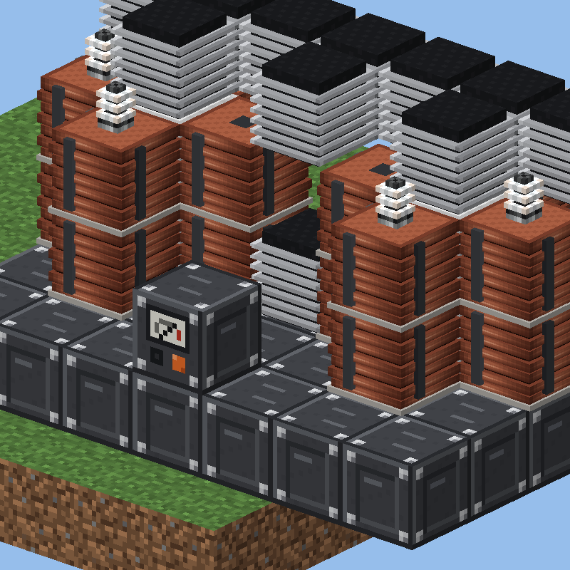
Why you need one
Power lost in a cable is current² × resistance. A transformer trades current for voltage: the voltage goes up ×n, the current goes down ÷n, and the power stays the same (minus small losses). Example: a 3 kW inverter at 220 V pushes about 13.6 A through the cable. After a 1:5 transformer, the same 3 kW travels at 1,100 V and only 2.7 A. That is 5× less current and 25× less heat in the cable. This is why real power lines run at high voltage.
What you need
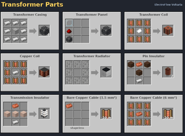
| Block | How many | Where it goes |
|---|---|---|
| Transformer Casing | 28 (7×4 base) | the base |
| Transformer Panel | 1 | ON TOP of the base, in the middle of the front row |
| Iron Block (vanilla) | 1 per layer, per side | the core: the CENTRE of each cross |
| Transformer Coil (or Copper Coil) | 4 per layer, per side | the 4 sides of each cross |
| Pin Insulator or Transmission Insulator | exactly 4 | 2 on top of the left coils (input), 2 on top of the right coils (output) |
| Transformer Radiator (optional) | up to 6 | corners of the crosses, the middle gap, or on top |
Both coil types work: the Transformer Coil (the ring-shaped one) and the Copper Coil. The shape (top view) 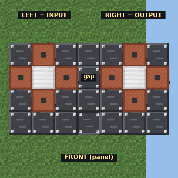 There are two cells shaped like a cross, one on each side. That is how a real transformer works: the copper winding is wrapped around a leg of the iron core. Stand in front of the panel and look at it:
- the LEFT cell is the primary, the INPUT (where power comes in);
- the RIGHT cell is the secondary, the OUTPUT (where power goes out).
Step 1 — base and panel
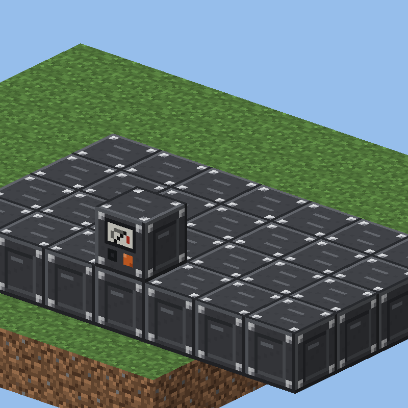 Place a 7 wide × 4 deep floor of Transformer Casing. That is 28 blocks.
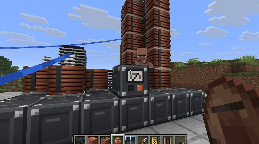
2. Place the Transformer Panel ON TOP of the base, in the middle of the front row (the 4th block from either side). Its screen faces you: this side is now the "front". The panel is the brain of the transformer. It checks the structure, shows readings and points out mistakes. Step 2 — the two cells (core + coils) 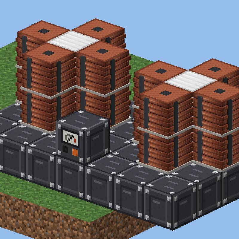
- On the base, left of the panel, build a cross: an Iron Block in the centre and a coil on each of its 4 sides. Leave the 4 corners empty.
- Build the same cross right of the panel. Keep the middle column between the two crosses (the "gap") free; you can leave it empty or fill it with a radiator or an iron block.
- Stack more layers to change the voltage. Each cell can be 1 to 6 layers tall, and every layer that has coils needs its iron block in the centre.
How the ratio works. The ratio is the number of coil blocks on the right divided by the number on the left:
| Left (input) | Right (output) | Ratio | 220 V becomes |
|---|---|---|---|
| 1 layer (4 coils) | 1 layer (4 coils) | 1:1 | 220 V (isolation only) |
| 1 layer (4) | 4 layers (16) | 1:4 | 880 V |
| 1 layer (4) | 5 layers (20) | 1:5 | 1,100 V (used in /electroflow demo) |
| 1 layer (4) | 6 layers (24) | 1:6 | 1,320 V |
| 1 coil only | 6 layers (24) | 1:24 | ~5,300 V (the maximum) |
| 5 layers (20) | 1 layer (4) | 5:1 | 1,100 V → 220 V (step-down) |
To step UP, put more coils on the right.
- To step DOWN, put more coils on the left.
- For the highest ratio, remove coils from the left cross until only 1 is left. That gives 24:1 = about 5.3 kV.
- Need even more voltage? Put two transformers in a row.
Step 3 — insulators and radiators
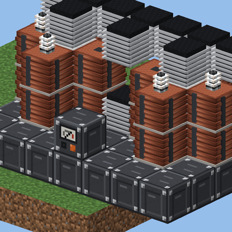
- Place 2 insulators on top of the LEFT cell's coils. This is the INPUT.
- Place 2 insulators on top of the RIGHT cell's coils. This is the OUTPUT.
- Insulators must sit directly on a coil (not on iron or a radiator).
- Each side needs exactly 2.
- Pin Insulator and Transmission Insulator both work.
- Optionally, add Transformer Radiators (up to 6) in the corners of the crosses, in the middle gap or on top. Each one adds +50 % rated power.
| Radiators | Rated power |
|---|---|
| 0 | 10 kVA |
| 2 | 20 kVA |
| 4 | 30 kVA |
| 6 (max) | 40 kVA |
- Right-click the panel.
- When the transformer is complete, it shows the coil count on each side, the ratio, the rated power and the number of radiators. While it is running, it also shows the input and output voltage, the load and the temperature.
- When something is wrong, it says what and gives the coordinates of the wrong block. Example messages:
- "Base incomplete"
- "Missing core"
- "Needs exactly 2 insulators on top of the LEFT cell"
Step 4 — wiring
A complete grid looks like this: Panels → Battery → Inverter (220 V AC) → LEFT insulators → transformer → RIGHT insulators → transmission line → step-down transformer → your loads
- Run a cable from the inverter's GREEN output to one of the LEFT insulators.
- You can leave the second LEFT insulator without a cable. An insulator with no cable means that end of the coil is grounded to the casing, just like a real pole transformer with one bushing. The current returns through the ground, so a single cable is enough.
- If you prefer, run 2 cables (the inverter's green output and −). The circuit is then isolated from ground.
- Connect the RIGHT insulators to your transmission line: Pin Insulators on poles, or Transmission Insulators on towers.
- At the other end, step the voltage back down. Use another buildable transformer with the coils reversed (more on the left), or a Pole Transformer (see below).
 Physics rules
- AC ONLY. A transformer only works with alternating current, which means the inverter output.
- If you connect a battery or a solar panel directly, the core saturates and the primary becomes a short circuit (only the wire's resistance). Nothing comes out, and it heats up.
- The panel warns: "receiving DIRECT current".
- Voltage ×n, current ÷n. The power is the same, minus winding losses.
- Overload heats it up. The transformer heats up when it runs above its rated power.
- At 120 °C it starts smoking.
- At 160 °C it trips, with a bang, smoke and fire.
- It turns back on by itself after 30 seconds.
- Add radiators if it keeps overheating.
- It hums while it is energized.
DANGER — keep your distance
- At 1,000 V or more, an insulator can strike an electric arc at you without touching it. An arc kills instantly, knocks you back, sets fire and cracks like lightning.
- The arc reaches about 0.3 block + 0.1 block per 1,000 V, with a maximum of 4 blocks. That is roughly 0.4 block at 1.1 kV, 0.8 block at 5.3 kV and 1.7 blocks at 13.8 kV.
- Metal armor increases the reach: the arc jumps to you from farther away.
- Below 1,000 V you only get shocked if you touch it. Damage depends on the current through your body: voltage ÷ (1,000 Ω body + the ground you stand on). 100 mA is lethal.
- Corona sparks around high-voltage insulators are your warning that they are live.
- Players in Creative and Spectator mode don't get shocked.
Creative shortcut (command)
Needs cheats/OP:
/electroflow transformadorbuilds a complete transformer 2 blocks in front of you, facing you: 2 layers on each side (1:1), with insulators and radiators. It clears the space for you./electroflow transformador <input> <output>lets you choose the layers on each side (1 to 6). Example:/electroflow transformador 1 5gives 1:5, so 220 V → 1,100 V.
The command word is "transformador" (Portuguese).
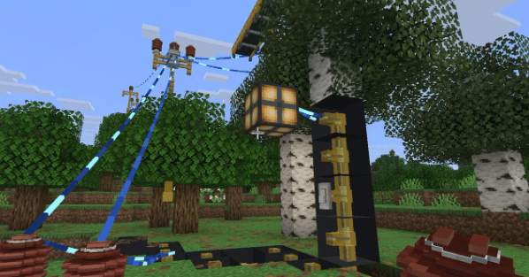
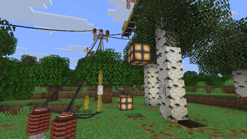
Bonus — Pole Transformer (stepping down to a house)
The Pole Transformer (15 kVA) is a single block that steps a line down to 220 V for houses.
Top bushing = HIGH VOLTAGE. It receives the line. Never connect it to anything at 220 V.
Sneak + right-click to choose the input voltage: 1,100 → 2,200 → 4,400 → 13,800 V. Match it to your line. For example, the
/electroflow demoline runs at 1,100 V.X1 = PHASE (220 V) and X2 = NEUTRAL, which is grounded at the pole.
Correct wiring: X1 → the phase terminal of the conduit/service entrance, and X2 → the neutral terminal. At the lamp: phase → black pin, neutral → light-blue pin.
What trips it:
- connecting X1 to X2 (phase to neutral) is a short circuit;
- so is anything above 18 kVA.
- Either way it trips for about 10 seconds with smoke, then resets.
Right-click (without sneaking) to see input, output, current and power.
Recipes
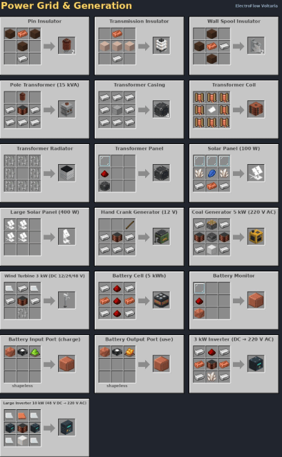
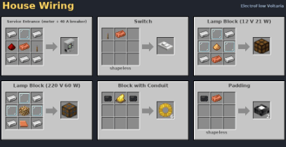
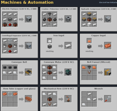
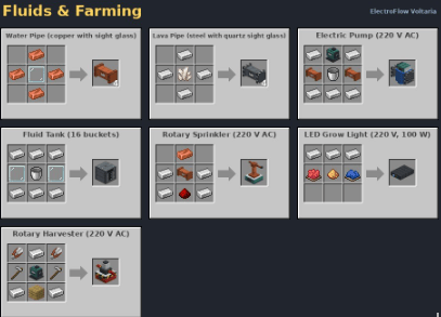
All recipes are also shown in JEI. Cables are sold by the meter: one craft gives 10 m. Insulated cables accept any dye color; the color doesn't change the electrical behavior. 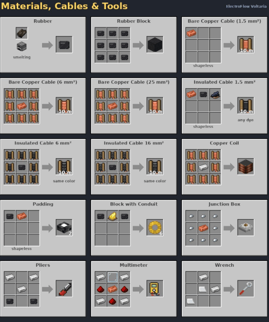
 Feedback, bug reports and screenshots of your builds are very welcome!
Project description from CurseForge.
Pick your setup
ElectroFlow(Voltaria) by Minecraft version and loader
Choose the version and loader you play, then open the matching release.
Minecraft version
1.21.1
1 loader buildCheck the dependencies, then try the file in a copied instance before changing a world you care about.
Recent files
ElectroFlow(Voltaria) versions and loaders
electroflowvoltaria-1.0.0-beta-mc1.21.1.jar
18 Nov 2026
Client Source doesn’t say Server Source doesn’t say Dependencies No extras listed Listed on Release listing
Check the 1.21.1 · NeoForge setup 1.21.1NeoForge release
electroflowvoltaria-1.0.0-beta.jar
18 Nov 2026
Client Source doesn’t say Server Source doesn’t say Dependencies No extras listed Listed on Release listing
Check the 26.3 · NeoForge setup NeoForge26.3 release
Looking for an older file? The official CurseForge project page is in Resources.
 mod
CurseForge · Minecraft
Phoenix Excavate
A simple and easy to use VeinMiner mod with powerful config and ingame settings.
 mod
CurseForge · Minecraft
Artisans
Adds various items and blocks across different crafts.
 mod
CurseForge · Minecraft
Create Riftborne
An addon for Create Aeronautics. A Rift Engine for ship teleportation, Stress generation, gravity tools, teleporters, a hostile Rift dimension to explore, and a lot more.